| Main |
| Range of Product |
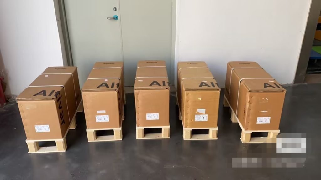
Altivar 32 |
| Product or Component Type |
Variable speed drive |
| product destination |
Synchronous motors |
| Asynchronous motors |
| Product Specific Application |
Complex machines |
| Function Available |
– |
| Assembly style |
With heat sink |
| Component name |
ATV32 |
| EMC filter |
Class C2 EMC filter integrated |
| Phase |
3 phase |
| [Us] rated supply voltage |
380…500 V – 15…10 % |
| Supply voltage limits |
323…550 V |
| Supply frequency |
50…60 Hz – 5…5 % |
| Network Frequency |
47.5…63 Hz |
| Motor power kW |
15 kW 380…480 V |
| Maximum Horse Power Rating |
20 hp 380…480 V |
| Complementary |
| Line current |
33.3 A 500 V 3 phase 15 kW / 20 hp |
| 47.3 A 380 V 3 phase 15 kW / 20 hp |
| Apparent power |
41 kVA 500 V 3 phase 15 kW / 20 hp |
| Prospective line Isc |
22 kA 3 phase |
| Nominal output current |
33 A 4 kHz 500 V 15 kW / 20 hp |
| Maximum transient current |
49.5 A 60 s 15 kW / 20 hp |
| Output frequency |
0.0005…0.599 kHz |
| Nominal switching frequency |
4 kHz |
| Switching frequency |
2…16 kHz adjustable |
| Speed range |
1…100 asynchronous motor in open-loop mode |
| Speed accuracy |
+/- 10 % of nominal slip 0.2 Tn to Tn |
| Torque accuracy |
+/- 15 % |
| Transient overtorque |
170…200 % |
| Braking torque |
<= 170 % with braking resistor |
| Asynchronous motor control profile |
Voltage/frequency ratio, 2 points |
| Flux vector control without sensor – Energy Saving, NoLoad law |
| Flux vector control without sensor, standard |
| Voltage/frequency ratio, 5 points |
| Voltage/frequency ratio – Energy Saving, quadratic U/f |
| Synchronous motor control profile |
Vector control without sensor |
| Regulation loop |
Adjustable PID regulator |
| Motor slip compensation |
Not available in voltage/frequency ratio (2 or 5 points) |
| Automatic whatever the load |
| Adjustable 0…300 % |
| Local signalling |
1 LED red drive voltage |
| 1 LED green CANopen run |
| 1 LED red CANopen error |
| 1 LED red drive fault |
| Output voltage |
<= power supply voltage |
| Noise level |
43 dB 86/188/EEC |
| Insulation |
Electrical between power and control |
| Electrical connection |
Screw terminal 16 mm², AWG 6 power supply) |
| Screw terminal 0.5…1.5 mm², AWG 18…AWG 14 control) |
| Removable screw terminals 6…16 mm², AWG 8…AWG 6 motor/braking resistor) |
| Tightening torque |
4.4 lbf.in (0.5 N.m), 4.4 lb/ft control) |
| 10.6 lbf.in (1.2 N.m), 10.6 lb/ft motor/braking resistor) |
| 10.6 lbf.in (1.2 N.m), 10.6 lb/ft power supply) |
| Supply |
Internal supply for reference potentiometer (1 to 10 kOhm) 10.5 V DC +/- 5 %, <10 mA overload and short-circuit protection |
| Analogue input number |
3 |
| Analogue input type |
AI1 voltage 0…10 V DC 30000 Ohm 10 bits |
| AI2 bipolar differential voltage +/- 10 V DC 30000 Ohm 10 bits |
| AI3 current 0…20 mA (or 4-20 mA, x-20 mA, 20-x mA or other patterns by configuration) 250 Ohm 10 bits |
| Sampling duration |
2 ms AI1, AI2, AI3) – analog |
| 2 ms AO1) – analog |
| Response time |
LI1…LI6 8 ms +/- 0.7 ms logic |
| R1A, R1B, R1C 2 ms relay |
| R2A, R2C 2 ms relay |
| Accuracy |
+/- 0.2 % AI1, AI2, AI3) for a temperature of -10…60 °C |
| +/- 0.5 % AI1, AI2, AI3) for a temperature of 25 °C |
| +/- 1 % AO1) for a temperature of 25 °C |
| +/- 2 % AO1) for a temperature of -10…60 °C |
| Linearity error |
+/- 0.2…0.5 % of maximum value AI1, AI2, AI3) |
| +/- 0.3 % AO1) |
| Analogue output number |
1 |
| Analogue output type |
AO1 software-configurable current 0…20 mA 800 Ohm 10 bits |
| AO1 software-configurable voltage 0…10 V 470 Ohm 10 bits |
| Discrete output number |
3 |
| Discrete output type |
Configurable relay logic R1A, R1B, R1C) NO/NC – 100000 cycles |
| Configurable relay logic R2A, R2B) NO – 100000 cycles |
| Logic LO) |
| Minimum switching current |
5 mA 24 V DC configurable relay logic |
| Maximum switching current |
R1 3 A 250 V AC resistive, cos phi = 1 |
| R1 4 A 30 V DC resistive, cos phi = 1 |
| R1, R2 2 A 250 V AC inductive, cos phi = 0.4 |
| R1, R2 2 A 30 V DC inductive, cos phi = 0.4 |
| R2 5 A 250 V AC resistive, cos phi = 1 |
| R2 5 A 30 V DC resistive, cos phi = 1 |
| Discrete input number |
7 |
| Discrete input type |
Programmable (sink/source) LI1…LI4)24…30 V DC level 1 PLC |
| Programmable as pulse input 20 kpps LI5)24…30 V DC level 1 PLC |
| Switch-configurable PTC probe LI6)24…30 V DC |
| Safe torque off STO)24…30 V DC – 1500 Ohm |
| Discrete input logic |
Negative logic (sink) LI1…LI6), > 19 V, < 13 V |
| Positive logic (source) LI1…LI6), < 5 V, > 11 V |
| Acceleration and deceleration ramps |
Deceleration ramp automatic stop DC injection |
| Deceleration ramp adaptation |
| U |
| S |
| Linear |
| Ramp switching |
| CUS |
| Braking to standstill |
By DC injection |
| Protection type |
Input phase breaks drive |
| Overcurrent between output phases and earth drive |
| Overheating protection drive |
| Short-circuit between motor phases drive |
| Thermal protection drive |
| Communication Port Protocol |
CANopen |
| Modbus |
| Connector type |
1 RJ45 on front face)Modbus/CANopen |
| Physical interface |
2-wire RS 485 Modbus |
| Transmission frame |
RTU Modbus |
| Type of polarization |
No impedance Modbus |
| Number of addresses |
1…127 CANopen |
| 1…247 Modbus |
| Method of access |
Slave CANopen |
| Electromagnetic compatibility |
1.2/50 µs – 8/20 µs surge immunity test, level 3 IEC 61000-4-5 |
| Conducted radio-frequency immunity test, level 3 IEC 61000-4-6 |
| Electrical fast transient/burst immunity test, level 4 IEC 61000-4-4 |
| Electrostatic discharge immunity test, level 3 IEC 61000-4-2 |
| Radiated radio-frequency electromagnetic field immunity test, level 3 IEC 61000-4-3 |
| Voltage dips and interruptions immunity test IEC 61000-4-11 |
| Width |
7.09 in (180 mm) |
| Height |
15.9 in (404 mm) |
| Depth |
9.1 in (232 mm) |
| Net Weight |
19.4 lb(US) (8.8 kg) |
| Option card |
Communication card CANopen daisy chain |
| Communication card CANopen open style |
| Communication card DeviceNet |
| Communication card EtherNet/IP |
| Communication card Profibus DP V1 |
| Functionality |
Mid |
| Specific application |
Other applications |
| Environment |
| Standards |
EN 55011 class A group 1 |
| EN/IEC 61800-3 |
| EN 61800-3 environments 2 category C2 |
| EN/IEC 61800-5-1 |
| EN 61800-3 environments 1 category C2 |
| Product Certifications |
UL |
| NOM 117 |
| CSA |
| C-tick |
| GOST |
| Marking |
CE |
| Pollution degree |
2 EN/IEC 61800-5-1 |
| IP degree of protection |
IP20 EN/IEC 61800-5-1 |
| Vibration resistance |
1 gn 13…200 Hz) EN/IEC 60068-2-6 |
| 1.5 mm peak to peak 3…13 Hz) EN/IEC 60068-2-6 |
| Shock resistance |
15 gn 11 msEN/IEC 60068-2-27 |
| Relative humidity |
5…95 % without condensation IEC 60068-2-3 |
| 5…95 % without dripping water IEC 60068-2-3 |
| Ambient air temperature for operation |
14…122 °F (-10…50 °C) without derating |
| 122…140 °F (50…60 °C) with derating factor |
| Ambient Air Temperature for Storage |
-13…158 °F (-25…70 °C) |
| Operating altitude |
<= 3280.84 ft (1000 m) without derating |
| 3280.84…9842.52 ft (1000…3000 m) with current derating 1 % per 100 m |
| Operating position |
Vertical +/- 10 degree |