| Main |
| Device short name |
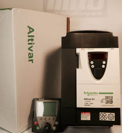
ATV71 |
| Product destination |
Synchronous motors |
| Asynchronous motors |
| Network number of phases |
3 phases |
| Supply voltage limits |
323…528 V |
| Supply frequency |
50…60 Hz – 5…5 % |
| Motor power kW |
5.5 kW, 3 phases at 380…480 V |
| Motor power hp |
7.5 hp, 3 phases at 380…480 V |
| Line current |
20.3 A for 380 V 3 phases 5.5 kW / 7.5 hp |
| 17 A for 480 V 3 phases 5.5 kW / 7.5 hp |
| Range of product |
Altivar Lift |
| Product or component type |
Variable speed drive |
| Product specific application |
Lift |
| Variant |
With integrated 7-segment display terminal |
| Communication port protocol |
Modbus |
| CANopen |
| [Us] rated supply voltage |
380…480 V – 15…10 % |
| EMC filter |
Integrated |
| Complementary |
| Apparent power |
13.4 kVA at 380 V 3 phases 5.5 kW / 7.5 hp |
| Prospective line Isc |
22 kA for 3 phases |
| Nominal output current |
14.3 A at 4 kHz 380 V 3 phases 5.5 kW / 7.5 hp |
| 11 A at 4 kHz 460 V 3 phases 5.5 kW / 7.5 hp |
| Maximum transient current |
19.4 A for 2 s 3 phases / 5.5 kW / 7.5 hp |
| Speed drive output frequency |
0…599 Hz |
| Speed range |
1…100 for asynchronous motor in open-loop mode, without speed feedback |
| 1…50 for synchronous motor in open-loop mode, without speed feedback |
| 1…1000 for asynchronous motor in closed-loop mode with encoder feedback |
| Torque accuracy |
+/- 5 % in closed-loop mode with encoder feedback |
| +/- 15 % in open-loop mode, without speed feedback |
| Transient overtorque |
170 %, +/- 10 % for 60 s |
| 220 %, +/- 10 % for 2 s |
| Braking torque |
30 % without braking resistor |
| <= 150 % with braking or hoist resistor |
| Local signalling |
1 LED (red) for drive voltage |
| Output voltage |
<= power supply voltage |
| Insulation |
Electrical between power and control |
| type of cable for external connection |
Without mounting kit: 1 wire(s)IEC cable at 45 °C, copper 90 °C / XLPE/EPR |
| Without mounting kit: 1 wire(s)IEC cable at 45 °C, copper 70 °C / PVC |
| With an IP21 or an IP31 kit: 3 wire(s)IEC cable at 40 °C, copper 70 °C / PVC |
| With a NEMA Type1 kit: 3 wire(s)UL 508 cable at 40 °C, copper 75 °C / PVC |
| Electrical connection |
Terminal, clamping capacity: 2.5 mm², AWG 14 (AI1-/AI1+, AI2, AO1, R1A, R1B, R1C, R2A, R2B, LI1…LI6, PWR) |
| Terminal, clamping capacity: 6 mm², AWG 8 (L1/R, L2/S, L3/T, U/T1, V/T2, W/T3, PC/-, PO, PA/+, PA, PB) |
| Tightening torque |
3 N.m, 26.5 lb.in (L1/R, L2/S, L3/T, U/T1, V/T2, W/T3, PC/-, PO, PA/+, PA, PB) |
| 0.6 N.m (AI1-/AI1+, AI2, AO1, R1A, R1B, R1C, R2A, R2B, LI1…LI6, PWR) |
| Supply |
Internal supply for reference potentiometer (1 to 10 kOhm): 10.5 V DC +/- 5 %, <10 A, protection type: overload and short-circuit protection |
| Internal supply: 24 V DC (21…27 V), <200 A, protection type: overload and short-circuit protection |
| Sampling duration |
2 ms +/- 0.5 ms (LI6)if configured as logic input – discrete input(s) |
| 2 ms +/- 0.5 ms (LI1…LI5) – discrete input(s) |
| 2 ms +/- 0.5 ms (AI1-/Al1+) – analog input(s) |
| 2 ms +/- 0.5 ms (Al2) – analog input(s) |
| Response time |
R1A, R1B, R1C 7 ms, tolerance +/- 0.5 ms for discrete output(s) |
| R2A, R2B 7 ms, tolerance +/- 0.5 ms for discrete output(s) |
| AO1 2 ms, tolerance +/- 0.5 ms for analog output(s) |
| <= 100 ms in STO (Safe Torque Off) |
| Accuracy |
+/- 0.6 % (AI1-/Al1+) for a temperature variation 60 °C |
| +/- 0.6 % (AI2) for a temperature variation 60 °C |
| +/- 1 % (AO1) for a temperature variation 60 °C |
| Linearity error |
+/- 0.15 % of maximum value (AI1-/Al1+, AI2) |
| +/- 0.2 % (AO1) |
| Analogue output type |
AO1 software-configurable voltage: 0…10 V DC, impedance: 470 Ohm, resolution 10 bits |
| AO1 software-configurable current: 0…20 mA, impedance: 500 Ohm, resolution 10 bits |
| AO1 software-configurable logic output 10 V 20 A |
| Discrete output type |
Configurable relay logic: (R1A, R1B, R1C) NO/NC – 100000 cycles |
| Configurable relay logic: (R2A, R2B) NO – 100000 cycles |
| Minimum switching current |
3 mA at 24 V DC for configurable relay logic |
| Maximum switching current |
5 A at 250 V AC on resistive load – cos phi = 1 – L/R = 0 ms (R1, R2) |
| 5 A at 30 V DC on resistive load – cos phi = 1 – L/R = 0 ms (R1, R2) |
| 2 A at 250 V AC on inductive load – cos phi = 0.4 – L/R = 7 ms (R1, R2) |
| 2 A at 30 V DC on inductive load – cos phi = 0.4 – L/R = 7 ms (R1, R2) |
| Discrete input type |
Programmable (LI1…LI5)24 V DC, with level 1 PLC – 3500 Ohm |
| Switch-configurable (LI6)24 V DC, with level 1 PLC – 3500 Ohm |
| Switch-configurable PTC probe (LI6) – 0…6 probes – 1500 Ohm |
| Safety input (PWR)24 V DC – 1500 Ohm |
| Discrete input logic |
Positive logic (LI6)if configured as logic input, < 5 V (state 0), > 11 V (state 1) |
| Negative logic (LI6)if configured as logic input, > 16 V (state 0), < 10 V (state 1) |
| Positive logic (LI1…LI5), < 5 V (state 0), > 11 V (state 1) |
| Negative logic (LI1…LI5), > 16 V (state 0), < 10 V (state 1) |
| Positive logic (PWR), < 2 V (state 0), > 17 V (state 1) |
| Dielectric strength |
3535 V DC between earth and power terminals |
| 5092 V DC between control and power terminals |
| Insulation resistance |
> 1 mOhm 500 V DC for 1 minute to earth |
| Frequency resolution |
Display unit: 0.1 Hz |
| Analog input: 0.024/50 Hz |
| Connector type |
1 RJ45 (on front face) for Modbus |
| 1 RJ45 (on terminal) for Modbus |
| Male SUB-D 9 on RJ45 for CANopen |
| Physical interface |
2-wire RS 485 for Modbus |
| Transmission frame |
RTU for Modbus |
| Transmission rate |
9600 bps, 19200 bps for Modbus on front face |
| 4800 bps, 9600 bps, 19200 bps, 38.4 Kbps for Modbus on terminal |
| 20 kbps, 50 kbps, 125 kbps, 250 kbps, 500 kbps, 1 Mbps for CANopen |
| Data format |
8 bits, 1 stop, even parity for Modbus on front face |
| 8 bits, odd even or no configurable parity for Modbus on terminal |
| Type of polarization |
No impedance for Modbus |
| Number of addresses |
1…247 for Modbus |
| 1…127 for CANopen |
| control options |
Communication card for Modbus TCP |
| Communication card for Fipio |
| Communication card for Modbus/Uni-Telway |
| Communication card for Modbus Plus |
| Communication card for EtherNet/IP |
| Communication card for DeviceNet |
| Communication card for Profibus DP |
| Communication card for Profibus DP V1 |
| Communication card for Interbus-S |
| Communication card for CC-Link |
| Interface card for encoder |
| I/O extension card |
| Controller inside programmable card |
| Overhead crane card |
| Discrete input number |
7 |
| Discrete output number |
2 |
| Analogue input number |
2 |
| Analogue input type |
AI2 software-configurable voltage: 0…10 V DC 24 V max, impedance: 30000 Ohm, resolution 11 bits |
| AI1-/Al1+ bipolar differential voltage: +/- 10 V DC 24 V max, resolution 11 bits + sign |
| AI2 software-configurable current: 0…20 mA, impedance: 242 Ohm, resolution 11 bits |
| Analogue output number |
1 |
| Method of access |
Slave CANopen |
| Asynchronous motor control profile |
Flux vector control with sensor, standard |
| Flux vector control without sensor, ENA (energy Adaptation) system |
| Voltage/frequency ratio, 5 points |
| Voltage/frequency ratio – Energy Saving, quadratic U/f |
| Voltage/frequency ratio, 2 points |
| Flux vector control without sensor, 2 points |
| Flux vector control without sensor, standard |
| Synchronous motor control profile |
Vector control with sensor, standard |
| Vector control without sensor, standard |
| Acceleration and deceleration ramps |
Automatic adaptation of ramp if braking capacity exceeded, by using resistor |
| Linear adjustable separately from 0.01 to 9000 s |
| S, U or customized |
| Motor slip compensation |
Suppressable |
| Automatic whatever the load |
| Not available in voltage/frequency ratio (2 or 5 points) |
| Adjustable |
| Switching frequency |
1…16 kHz adjustable |
| Nominal switching frequency |
8 kHz |
| Minimum braking resistance |
19 Ohm |
| Network frequency |
47.5…63 Hz |
| Protection type |
Overheating protection: drive |
| Thermal protection: drive |
| Short-circuit between motor phases: drive |
| Input phase breaks: drive |
| Overcurrent between output phases and earth: drive |
| Overvoltages on the DC bus: drive |
| Break on the control circuit: drive |
| Against exceeding limit speed: drive |
| Line supply undervoltage: drive |
| Line supply overvoltage: drive |
| Against input phase loss: drive |
| Thermal protection: motor |
| Motor phase break: motor |
| Power removal: motor |
| Environment |
| Pollution degree |
2 conforming to IEC 61800-5-1 |
| IP degree of protection |
IP20 on upper part without blanking plate on cover conforming to IEC 61800-5-1 |
| IP20 on upper part without blanking plate on cover conforming to IEC 60529 |
| IP21 conforming to IEC 61800-5-1 |
| IP21 conforming to IEC 60529 |
| IP41 on upper part conforming to IEC 61800-5-1 |
| IP41 on upper part conforming to IEC 60529 |
| IP54 on lower part conforming to IEC 61800-5-1 |
| IP54 on lower part conforming to IEC 60529 |
| Vibration resistance |
1.5 mm peak to peak (f= 3…13 Hz) conforming to IEC 60068-2-6 |
| 1 gn (f= 13…200 Hz) conforming to IEC 60068-2-6 |
| Shock resistance |
15 gn for 11 ms conforming to IEC 60068-2-27 |
| Noise level |
55.6 dB conforming to 86/188/EEC |
| Relative humidity |
5…95 % without condensation conforming to IEC 60068-2-3 |
| 5…95 % without dripping water conforming to IEC 60068-2-3 |
| Ambient air temperature for operation |
-10…50 °C (without derating) |
| Operating altitude |
<= 1000 m without derating |
| 1000…3000 m with current derating 1 % per 100 m |
| Operating position |
Vertical +/- 10 degree |
| product certifications |
UL |
| NOM 117 |
| CSA |
| C-Tick |
| GOST |
| marking |
CE |
| Standards |
IEC 60721-3-3 class 3S2 |
| EN 55011 class A group 2 |
| IEC 61800-5-1 |
| IEC 60721-3-3 class 3C1 |
| IEC 61800-3 |
| IEC 61800-3 environments 1 category C3 |
| UL Type 1 |
| IEC 61800-3 environments 2 category C3 |
| Assembly style |
With heat sink |
| Electromagnetic compatibility |
Electrostatic discharge immunity test level 3 conforming to IEC 61000-4-2 |
| Radiated radio-frequency electromagnetic field immunity test level 3 conforming to IEC 61000-4-3 |
| Electrical fast transient/burst immunity test level 4 conforming to IEC 61000-4-4 |
| 1.2/50 µs – 8/20 µs surge immunity test level 3 conforming to IEC 61000-4-5 |
| Conducted radio-frequency immunity test level 3 conforming to IEC 61000-4-6 |
| Voltage dips and interruptions immunity test conforming to IEC 61000-4-11 |
| Regulation loop |
Adjustable PI regulator |
| Speed accuracy |
+/- 0.01 % of nominal speed in closed-loop mode with encoder feedback 0.2 Tn to Tn |
| +/- 10 % of nominal slip without speed feedback 0.2 Tn to Tn |
| Ambient air temperature for storage |
-25…70 °C |