| Main |
| Range of Product |
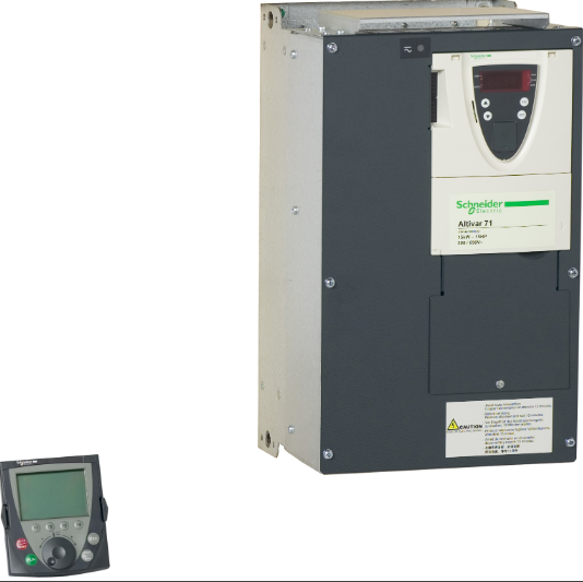
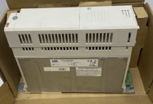
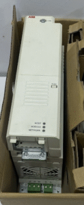
Altivar 71 |
| Product or Component Type |
Variable speed drive |
| Product Specific Application |
Complex, high-power machines |
| Component name |
ATV71 |
| Motor power kW |
4 kW, single phase 200…240 V |
| 5.5 kW, 3 phase 200…240 V |
| Maximum Horse Power Rating |
5 hp, single phase 200…240 V |
| 7.5 hp, 3 phase 200…240 V |
| Maximum motor cable length |
164.04 ft (50 m) shielded cable |
| 328.08 ft (100 m) unshielded cable |
| power supply voltage |
200…240 V – 15…10 % |
| Phase |
3 phase |
| Single phase |
| Line current |
29.9 A 240 V single phase 4 kW / 5 hp |
| 30.8 A 240 V 3 phase 5.5 kW / 7.5 hp |
| 34.9 A 200 V single phase 4 kW / 5 hp |
| 35 A 200 V 3 phase 5.5 kW / 7.5 hp |
| EMC filter |
Integrated |
| Assembly style |
With heat sink |
| Apparent power |
7 kVA 240 V single phase 4 kW / 5 hp |
| 12.8 kVA 240 V 3 phase 5.5 kW / 7.5 hp |
| Prospective line Isc |
22 kA 3 phase |
| 5 kA single phase |
| Nominal output current |
17.5 A 4 kHz 230 V single phase 4 kW / 5 hp |
| 27.5 A 4 kHz 230 V 3 phase 5.5 kW / 7.5 hp |
| Maximum transient current |
26.3 A 60 s single phase 4 kW / 5 hp |
| 28.8 A 2 s single phase 4 kW / 5 hp |
| 41.3 A 60 s 3 phase 5.5 kW / 7.5 hp |
| 45.3 A 2 s 3 phase 5.5 kW / 7.5 hp |
| Output frequency |
0.1…599 Hz |
| Nominal switching frequency |
4 kHz |
| Switching frequency |
1…16 kHz adjustable |
| 4…16 kHz with derating factor |
| Asynchronous motor control profile |
ENA (Energy adaptation) system for unbalanced loads |
| Sensorless flux vector control (SFVC) (voltage or current vector) |
| Voltage/frequency ratio (2 or 5 points) |
| Flux vector control (FVC) with sensor (current vector) |
| Type of polarization |
No impedance Modbus |
| Complementary |
| Product destination |
Asynchronous motors |
| Synchronous motors |
| power supply voltage limits |
170…264 V |
| power supply frequency |
50…60 Hz – 5…5 % |
| power supply frequency limits |
47.5…63 Hz |
| Speed range |
1…100 asynchronous motor in open-loop mode, without speed feedback |
| 1…1000 asynchronous motor in closed-loop mode with encoder feedback |
| 1…50 synchronous motor in open-loop mode, without speed feedback |
| Speed accuracy |
+/- 0.01 % of nominal speed in closed-loop mode with encoder feedback 0.2 Tn to Tn |
| +/- 10 % of nominal slip without speed feedback 0.2 Tn to Tn |
| Torque accuracy |
+/- 15 % in open-loop mode, without speed feedback |
| +/- 5 % in closed-loop mode with encoder feedback |
| Transient overtorque |
170 % +/- 10 % 60 s every 10 minutes |
| 220 % +/- 10 % 2 s |
| Braking torque |
<= 150 % with braking or hoist resistor |
| 30 % without braking resistor |
| Synchronous motor control profile |
Vector control without speed feedback |
| Regulation loop |
Adjustable PI regulator |
| Motor slip compensation |
Adjustable |
| Suppressable |
| Automatic whatever the load |
| Not available in voltage/frequency ratio (2 or 5 points) |
| diagnostic |
for drive voltage 1 LED (red) |
| Output voltage |
<= power supply voltage |
| Insulation |
Electrical between power and control |
| type of cable for mounting in an enclosure |
With a NEMA Type1 kit 3 UL 508 cable 104.0000000000 °F (40 °C), copper 75 °C / PVC |
| With an IP21 or an IP31 kit 3 IEC cable 104.0000000000 °F (40 °C), copper 70 °C / PVC |
| Without mounting kit 1 IEC cable 113.0000000000 °F (45 °C), copper 70 °C / PVC |
| Without mounting kit 1 IEC cable 113.0000000000 °F (45 °C), copper 90 °C / XLPE/EPR |
| Electrical connection |
Terminal 2.5 mm², AWG 14 AI1-/AI1+, AI2, AO1, R1A, R1B, R1C, R2A, R2B, LI1…LI6, PWR) |
| Terminal 6 mm², AWG 8 L1/R, L2/S, L3/T, U/T1, V/T2, W/T3, PC/-, PO, PA/+, PA, PB) |
| Tightening torque |
5.3 lbf.in (0.6 N.m) AI1-/AI1+, AI2, AO1, R1A, R1B, R1C, R2A, R2B, LI1…LI6, PWR) |
| 26.6 lbf.in (3 N.m), 26.5 lb.in L1/R, L2/S, L3/T, U/T1, V/T2, W/T3, PC/-, PO, PA/+, PA, PB) |
| Supply |
Internal supply for reference potentiometer (1 to 10 kOhm) 10.5 V DC +/- 5 %, <10 mA overload and short-circuit protection |
| Internal supply 24 V DC 21…27 V), <200 mA overload and short-circuit protection |
| Analogue input number |
2 |
| Analogue input type |
AI1-/Al1+ bipolar differential voltage +/- 10 V DC 24 V max 11 bits + sign |
| AI2 software-configurable current 0…20 mA 242 Ohm 11 bits |
| AI2 software-configurable voltage 0…10 V DC 24 V max 30000 Ohm 11 bits |
| input sampling time |
2 ms +/- 0.5 ms AI1-/Al1+) – analog |
| 2 ms +/- 0.5 ms Al2) – analog |
| 2 ms +/- 0.5 ms LI1…LI5) – discrete |
| 2 ms +/- 0.5 ms LI6)if configured as logic input – discrete |
| Response time |
<= 100 ms in STO (Safe Torque Off) |
| AO1 2 ms +/- 0.5 ms analog |
| R1A, R1B, R1C 7 ms +/- 0.5 ms discrete |
| R2A, R2B 7 ms +/- 0.5 ms discrete |
| absolute accuracy precision |
+/- 0.6 % AI1-/Al1+) for a temperature variation 60 °C |
| +/- 0.6 % AI2) for a temperature variation 60 °C |
| +/- 1 % AO1) for a temperature variation 60 °C |
| Linearity error |
+/- 0.15 % of maximum value AI1-/Al1+, AI2) |
| +/- 0.2 % AO1) |
| Analogue output number |
1 |
| Analogue output type |
AO1 software-configurable logic output 10 V 20 mA |
| AO1 software-configurable current 0…20 mA 500 Ohm 10 bits |
| AO1 software-configurable voltage 0…10 V DC 470 Ohm 10 bits |
| Discrete output number |
2 |
| Discrete output type |
Configurable relay logic R1A, R1B, R1C) NO/NC – 100000 cycles |
| Configurable relay logic R2A, R2B) NO – 100000 cycles |
| Minimum switching current |
3 mA 24 V DC configurable relay logic |
| Maximum switching current |
R1, R2 2 A 250 V AC inductive, cos phi = 0.4 |
| R1, R2 2 A 30 V DC inductive, cos phi = 0.4 |
| R1, R2 5 A 250 V AC resistive, cos phi = 1 |
| R1, R2 5 A 30 V DC resistive, cos phi = 1 |
| Discrete input number |
7 |
| Discrete input type |
LI1…LI5 programmable 24 V DC level 1 PLC 3500 Ohm |
| LI6 switch-configurable 24 V DC level 1 PLC 3500 Ohm |
| LI6 switch-configurable PTC probe 0…6 1500 Ohm |
| PWR safety input 24 V DC 1500 Ohm ISO 13849-1 level d |
| Discrete input logic |
Negative logic (sink) LI1…LI5), > 16 V, < 10 V |
| Positive logic (source) LI1…LI5), < 5 V, > 11 V |
| Negative logic (sink) LI6)if configured as logic input, > 16 V, < 10 V |
| Positive logic (source) LI6)if configured as logic input, < 5 V, > 11 V |
| Acceleration and deceleration ramps |
Automatic adaptation of ramp if braking capacity exceeded, by using resistor |
| S, U or customized |
| Linear adjustable separately from 0.01 to 9000 s |
| Braking to standstill |
By DC injection |
| Protection type |
Against exceeding limit speed drive |
| Against input phase loss drive |
| Break on the control circuit drive |
| Input phase breaks drive |
| Line supply overvoltage drive |
| Line supply undervoltage drive |
| Overcurrent between output phases and earth drive |
| Overheating protection drive |
| Overvoltages on the DC bus drive |
| Short-circuit between motor phases drive |
| Thermal protection drive |
| Motor phase break motor |
| Power removal motor |
| Thermal protection motor |
| Insulation resistance |
> 1 mOhm 500 V DC for 1 minute to earth |
| Frequency resolution |
Analog input 0.024/50 Hz |
| Display unit 0.1 Hz |
| Communication Port Protocol |
CANopen |
| Modbus |
| Connector type |
1 RJ45 on front face)Modbus |
| 1 RJ45 on terminal)Modbus |
| Male SUB-D 9 on RJ45CANopen |
| Physical interface |
2-wire RS 485 Modbus |
| Transmission frame |
RTU Modbus |
| Transmission rate |
4800 bps, 9600 bps, 19200 bps, 38.4 Kbps Modbus on terminal |
| 9600 bps, 19200 bps Modbus on front face |
| 20 kbps, 50 kbps, 125 kbps, 250 kbps, 500 kbps, 1 Mbps CANopen |
| Data format |
8 bits, 1 stop, even parity Modbus on front face |
| 8 bits, odd even or no configurable parity Modbus on terminal |
| Number of addresses |
1…127 CANopen |
| 1…247 Modbus |
| Method of access |
Slave CANopen |
| marking |
CE |
| Operating position |
Vertical +/- 10 degree |
| Height |
11.6 in (295 mm) |
| Depth |
7.4 in (187 mm) |
| Width |
6.9 in (175 mm) |
| Product Weight |
12.1 lb(US) (5.5 kg) |
| Functionality |
Full |
| Specific application |
Other applications |
| Option card |
Communication card CC-Link |
| Controller inside programmable card |
| Communication card DeviceNet |
| Communication card EtherNet/IP |
| Communication card Fipio |
| I/O extension card |
| Communication card Interbus-S |
| Interface card for encoder |
| Communication card Modbus Plus |
| Communication card Modbus TCP |
| Communication card Modbus/Uni-Telway |
| Overhead crane card |
| Communication card Profibus DP |
| Communication card Profibus DP V1 |
| Environment |
| Noise level |
55.6 dB 86/188/EEC |
| Dielectric strength |
2830 V DC between earth and power terminals |
| 4230 V DC between control and power terminals |
| Electromagnetic compatibility |
1.2/50 µs – 8/20 µs surge immunity test level 3 IEC 61000-4-5 |
| Conducted radio-frequency immunity test level 3 IEC 61000-4-6 |
| Electrical fast transient/burst immunity test level 4 IEC 61000-4-4 |
| Electrostatic discharge immunity test level 3 IEC 61000-4-2 |
| Radiated radio-frequency electromagnetic field immunity test level 3 IEC 61000-4-3 |
| Voltage dips and interruptions immunity test IEC 61000-4-11 |
| Standards |
EN/IEC 61800-5-1 |
| EN 55011 class A group 2 |
| EN/IEC 61800-3 |
| IEC 60721-3-3 class 3C1 |
| IEC 60721-3-3 class 3S2 |
| EN 61800-3 environments 1 category C3 |
| EN 61800-3 environments 2 category C3 |
| UL Type 1 |
| Product Certifications |
UL |
| NOM 117 |
| GOST |
| CSA |
| C-tick |
| Pollution degree |
2 EN/IEC 61800-5-1 |
| IP degree of protection |
IP20 |
| Vibration resistance |
1 gn 13…200 Hz)EN/IEC 60068-2-6 |
| 1.5 mm peak to peak 3…13 Hz)EN/IEC 60068-2-6 |
| Shock resistance |
15 gn 11 ms EN/IEC 60068-2-27 |
| Relative humidity |
5…95 % without condensation IEC 60068-2-3 |
| 5…95 % without dripping water IEC 60068-2-3 |
| Ambient air temperature for operation |
14.0000000000…122.0000000000 °F (-10…50 °C) without derating) |
| Ambient Air Temperature for Storage |
-13.0000000000…158.0000000000 °F (-25…70 °C) |
| Operating altitude |
<= 3280.84 ft (1000 m) without derating |
| 3280.84…9842.52 ft (1000…3000 m) with current derating 1 % per 100 m |